555 Timer Schematic Diagram - Ic 555 timer ic is one of the most popular integrated circuit chip used for a variety of applications such as astable, monostable, bistable multivibrators, timer circuits, oscillators, pwm (pulse width modulation), ppm (pulse position modulation), square wave generator or pulse generator, etc.
byAdmin-
0
555 Timer Schematic Diagram - Ic 555 timer ic is one of the most popular integrated circuit chip used for a variety of applications such as astable, monostable, bistable multivibrators, timer circuits, oscillators, pwm (pulse width modulation), ppm (pulse position modulation), square wave generator or pulse generator, etc.. Therefore, the microcontroller 8051's pin diagram and explanation is given below. A total of 32 pins are set away into four ports such as p0, p1, p2 and p3. Four general purpose rectifier diode 1n4007 are used here to retify the ac input. Although, these component symbols change based on countries due to some common principles fixed by ansi & iec to signify the components. Jul 04, 2021 · designfast ebooks / tech tips faqs leap awards oscilloscope product finder ee podcasts ee webinars ee whitepapers ee calculators thermistor resistance calculator 555 timer calculator (astable mode) lm3914 calculator capacitor impedance calculator capacitor impedance calculator lm317 calculator all calculators
Pin diagram of 8051 microcontroller. Jul 04, 2021 · designfast ebooks / tech tips faqs leap awards oscilloscope product finder ee podcasts ee webinars ee whitepapers ee calculators thermistor resistance calculator 555 timer calculator (astable mode) lm3914 calculator capacitor impedance calculator capacitor impedance calculator lm317 calculator all calculators Another advantage that comes with a cloud application is cross device compatibility. 1n4007 has a peak repetitive reverse voltage of 1000v with an average rectified forward current of 1a. The transformer is used to step down the 230v ac to 13v ac.
A 555 Timer Ic Tutorial from groups.ist.utl.pt The difference from the standard design of a 555 timer is the resistance between pins 6 and 7 of the ic composed of p1, p2, r2, d1 and d2. Since the application is built on cloud, it gives the convenience of mobility and portability. Ic 555 timer ic is one of the most popular integrated circuit chip used for a variety of applications such as astable, monostable, bistable multivibrators, timer circuits, oscillators, pwm (pulse width modulation), ppm (pulse position modulation), square wave generator or pulse generator, etc. Dec 07, 2018 · 555 timer ic. Another advantage that comes with a cloud application is cross device compatibility. The circuit is an astable multivibrator with a 50% pulse duty cycle. The pin diagram of 8051 microcontroller consists of 40 pins as shown below. This is a pulse generator with adjustable duty cycle made with the 555 timer ic.
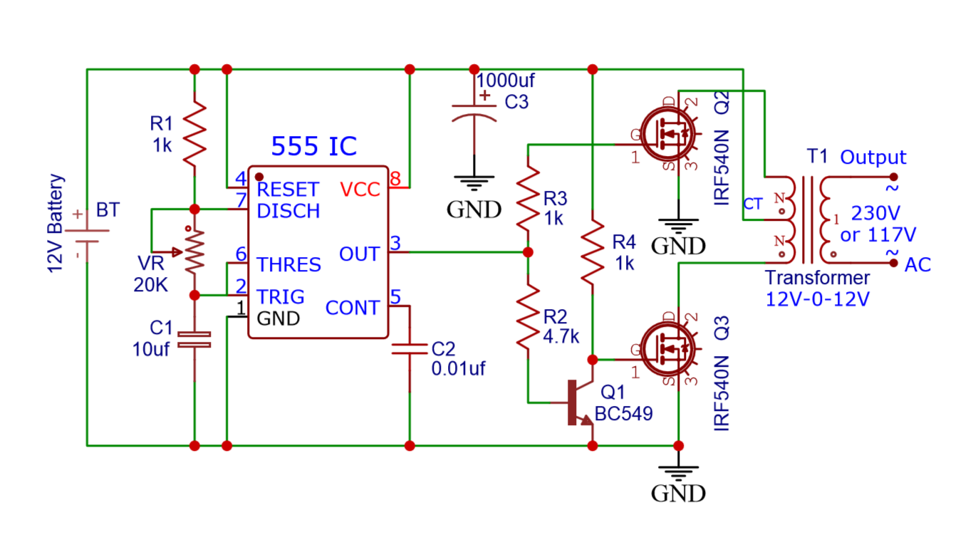
The transformer is used to step down the 230v ac to 13v ac.
Ic 555 timer ic is one of the most popular integrated circuit chip used for a variety of applications such as astable, monostable, bistable multivibrators, timer circuits, oscillators, pwm (pulse width modulation), ppm (pulse position modulation), square wave generator or pulse generator, etc. Pin diagram of 8051 microcontroller. So the time period after which this circuit will automatically turn on/off the output is fixed and can be found out by using the formula mentioned in the calculation section. The circuit is an astable multivibrator with a 50% pulse duty cycle. Therefore, the microcontroller 8051's pin diagram and explanation is given below. Another advantage that comes with a cloud application is cross device compatibility. The below figure is the schematic of a simple automatic on off timer with a fixed timing resistor and capacitor. Dec 07, 2018 · 555 timer ic. A total of 32 pins are set away into four ports such as p0, p1, p2 and p3. Nov 05, 2011 · they have over 70,000+ readily available schematic in their web database along with 15,000+ pspice libraries. This is a pulse generator with adjustable duty cycle made with the 555 timer ic. The pin diagram of 8051 microcontroller consists of 40 pins as shown below. Lets list out free circuit diagram drawing softwares first.
Pin diagram of 8051 microcontroller. So the time period after which this circuit will automatically turn on/off the output is fixed and can be found out by using the formula mentioned in the calculation section. Astable mode, monostable mode and bistable mode are the three modes of operation of ic 555. Since the application is built on cloud, it gives the convenience of mobility and portability. The below figure is the schematic of a simple automatic on off timer with a fixed timing resistor and capacitor.
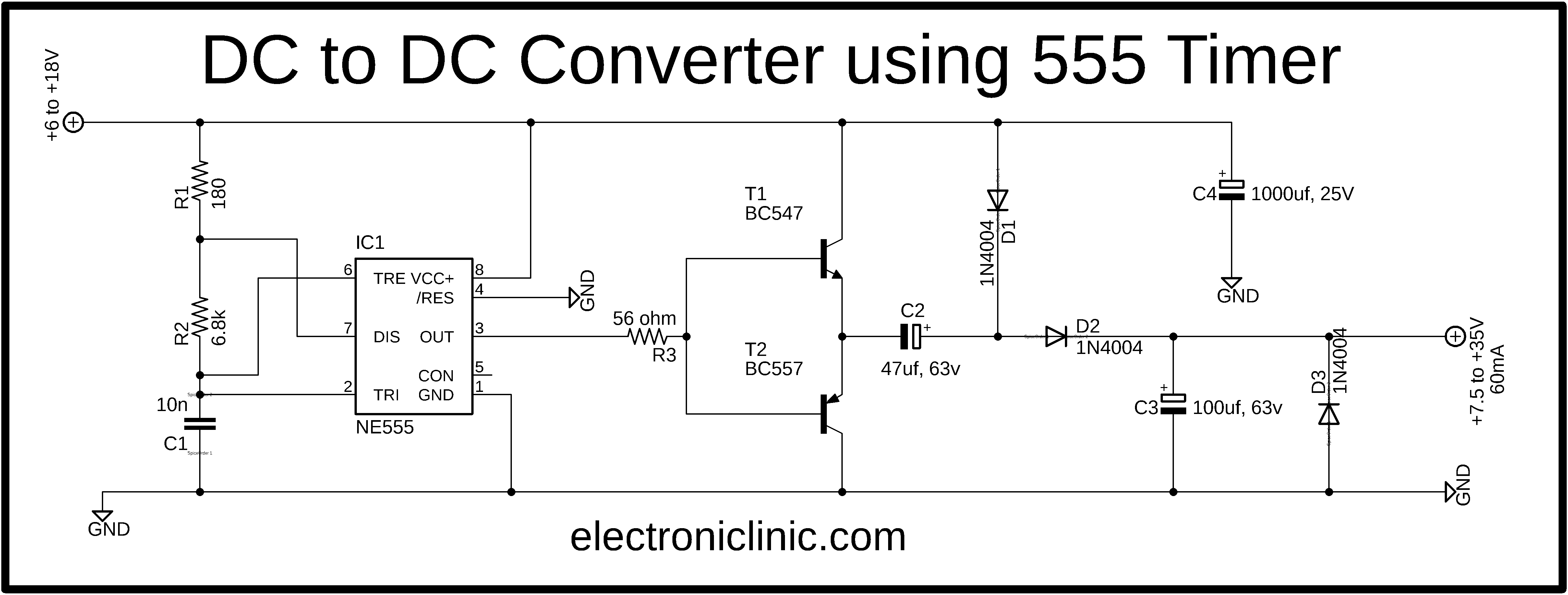
Simple Dc To Dc Converter Using 555 Time Ic 6v To 35 Volts Boost Converter from www.electroniclinic.com Lets list out free circuit diagram drawing softwares first. Another advantage that comes with a cloud application is cross device compatibility. Astable mode, monostable mode and bistable mode are the three modes of operation of ic 555. A total of 32 pins are set away into four ports such as p0, p1, p2 and p3. The below figure is the schematic of a simple automatic on off timer with a fixed timing resistor and capacitor. The transformer is used to step down the 230v ac to 13v ac. Dec 07, 2018 · 555 timer ic. Therefore, the microcontroller 8051's pin diagram and explanation is given below.
Lets list out free circuit diagram drawing softwares first.
Electronic circuit symbols are signs or drawings or pictograms of different components to signify electronic components in a schematic diagram of an electronic circuit. 1n4007 has a peak repetitive reverse voltage of 1000v with an average rectified forward current of 1a. The below figure is the schematic of a simple automatic on off timer with a fixed timing resistor and capacitor. Lets list out free circuit diagram drawing softwares first. Jul 04, 2021 · designfast ebooks / tech tips faqs leap awards oscilloscope product finder ee podcasts ee webinars ee whitepapers ee calculators thermistor resistance calculator 555 timer calculator (astable mode) lm3914 calculator capacitor impedance calculator capacitor impedance calculator lm317 calculator all calculators The transformer is used to step down the 230v ac to 13v ac. Therefore, the microcontroller 8051's pin diagram and explanation is given below. The circuit is an astable multivibrator with a 50% pulse duty cycle. The pin diagram of 8051 microcontroller consists of 40 pins as shown below. Four general purpose rectifier diode 1n4007 are used here to retify the ac input. Nov 05, 2011 · they have over 70,000+ readily available schematic in their web database along with 15,000+ pspice libraries. Although, these component symbols change based on countries due to some common principles fixed by ansi & iec to signify the components. Another advantage that comes with a cloud application is cross device compatibility.
Four general purpose rectifier diode 1n4007 are used here to retify the ac input. Dec 07, 2018 · 555 timer ic. Where, each port contains 8 pins. Electronic circuit symbols are signs or drawings or pictograms of different components to signify electronic components in a schematic diagram of an electronic circuit. The below figure is the schematic of a simple automatic on off timer with a fixed timing resistor and capacitor.
12v To 230v Inverter Circuit Diagram Using 555 Timer Ic Inverters from hackatronic.com The transformer is used to step down the 230v ac to 13v ac. The circuit is an astable multivibrator with a 50% pulse duty cycle. A total of 32 pins are set away into four ports such as p0, p1, p2 and p3. Although, these component symbols change based on countries due to some common principles fixed by ansi & iec to signify the components. 1n4007 has a peak repetitive reverse voltage of 1000v with an average rectified forward current of 1a. Pin diagram of 8051 microcontroller. This is a pulse generator with adjustable duty cycle made with the 555 timer ic. Lets list out free circuit diagram drawing softwares first.
The transformer is used to step down the 230v ac to 13v ac.
Four general purpose rectifier diode 1n4007 are used here to retify the ac input. Where, each port contains 8 pins. Jul 04, 2021 · designfast ebooks / tech tips faqs leap awards oscilloscope product finder ee podcasts ee webinars ee whitepapers ee calculators thermistor resistance calculator 555 timer calculator (astable mode) lm3914 calculator capacitor impedance calculator capacitor impedance calculator lm317 calculator all calculators Since the application is built on cloud, it gives the convenience of mobility and portability. The below figure is the schematic of a simple automatic on off timer with a fixed timing resistor and capacitor. The transformer is used to step down the 230v ac to 13v ac. Although, these component symbols change based on countries due to some common principles fixed by ansi & iec to signify the components. Dec 07, 2018 · 555 timer ic. Ic 555 timer ic is one of the most popular integrated circuit chip used for a variety of applications such as astable, monostable, bistable multivibrators, timer circuits, oscillators, pwm (pulse width modulation), ppm (pulse position modulation), square wave generator or pulse generator, etc. Pin diagram of 8051 microcontroller. Astable mode, monostable mode and bistable mode are the three modes of operation of ic 555. Nov 05, 2011 · they have over 70,000+ readily available schematic in their web database along with 15,000+ pspice libraries. So the time period after which this circuit will automatically turn on/off the output is fixed and can be found out by using the formula mentioned in the calculation section.
The difference from the standard design of a 555 timer is the resistance between pins 6 and 7 of the ic composed of p1, p2, r2, d1 and d2 555 timer schematic. The circuit is an astable multivibrator with a 50% pulse duty cycle.